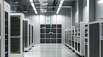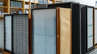
Global demand for controlled environments is reshaping how buyers evaluate an Ffu Filter Unit. Pharmaceutical production, semiconductor fabrication, biotechnology, and medical-device manufacturing all require stable airflow and measurable particle control. Grand View Research estimates that the global cleanroom technology market reached approximately USD 5.4 billion in 2023. Its forecast also indicates continued growth through 2030. MarketsandMarkets reports a similar expansion, driven by stricter contamination-control requirements and advanced manufacturing investments.
For global buyers, a manufacturer’s catalogue is not enough. Air volume, HEPA or ULPA efficiency, motor reliability, noise levels, energy use, and maintenance access require careful comparison. William Whyte, a respected cleanroom engineering author, wrote, “A cleanroom is a system, not simply a room.” That principle applies directly to every Ffu Filter Unit selection. A ceiling module can look excellent while performing poorly if installation gaps, uneven airflow, or weak validation remain unresolved.
This guide examines leading Ffu Filter Unit manufacturers serving international markets. It considers product engineering, testing evidence, customization, after-sales support, and supply-chain consistency. Certifications matter. So do factory records, replacement-filter availability, and documented airflow results. No ranking is perfect. Buyer priorities differ between a sterile filling line and a compact laboratory. The strongest supplier is not always the cheapest one. It is the company that can prove repeatable performance under real operating conditions. Data sheets help, but site experience often reveals the uncomfortable details. Expect differences. Verify every important claim.

An FFU’s real performance includes more than the filter grade. Buyers should request individual scan-test reports, airflow data, pressure-drop values, and motor specifications. A cleanroom unit may reach 99.95% efficiency during factory testing, yet poor sealing can reduce protection after installation. Gasket compression matters. So does housing flatness.
In practical procurement, compare airflow at the stated operating pressure.
Check whether testing follows EN 1822 or ISO 29463, and confirm the report’s serial number. The U.S. National Institute for Occupational Safety and Health emphasizes that filtration efficiency depends on test conditions, particle size, and airflow. This is easy to overlook. I would also question unusually low pressure-drop claims, because efficiency, airflow, noise, and energy use rarely improve together without trade-offs. A commissioning leak test remains necessary, even when the paperwork looks complete.
ISO 14644-1 Cleanroom Classes 5–8 and FFU Performance Requirements
ISO 14644-1 classifies cleanrooms by airborne particle concentration, not by FFU brand or appearance. Class 5 permits fewer particles than Class 8. Therefore, buyers must match FFU performance with the room’s process risk and production load.
A reliable FFU should provide stable airflow, suitable filter efficiency, and consistent pressure control. For many applications, HEPA filtration is common, while ULPA filtration may suit stricter processes. Verify the tested particle size, filter integrity, airflow uniformity, and leakage control. Do not rely only on catalogue figures. They can change after installation.
Commissioning data matters. Measure air velocity at several grid points, not just near the center. Check noise, vibration, power consumption, and alarm accuracy. A practical FFU selection also considers ceiling layout, maintenance access, replacement filters, and local electrical standards. Keep the system serviceable.
Some manufacturers report impressive airflow, but the result may depend on a clean filter and ideal pressure. Real rooms are less cooperative. Dust loading, poor sealing, and uneven ceiling panels can reduce performance. Buyers should request factory test records, installation guidance, calibration evidence, and clear warranty terms. Independent validation remains valuable, especially for Class 5 and Class 6 areas. Mistakes still happen. A small untested gap can undermine an otherwise carefully designed cleanroom.
| Category | Parameter | ISO 14644-1 Cleanroom Class | Global Buyer Evaluation Point | |||
|---|---|---|---|---|---|---|
| ISO Class 5 | ISO Class 6 | ISO Class 7 | ISO Class 8 | |||
| Airborne Particle Classification Limits | ||||||
| Particle concentration | Maximum permitted particles per m³ at ≥0.1 µm | 100,000 | 1,000,000 | N/A* | N/A* | Confirm the particle-size channels supported by the cleanroom certification plan. |
| Particle concentration | Maximum permitted particles per m³ at ≥0.2 µm | 23,700 | 237,000 | N/A* | N/A* | Use calibrated particle counters and a documented sampling location plan. |
| Particle concentration | Maximum permitted particles per m³ at ≥0.3 µm | 10,200 | 102,000 | N/A* | N/A* | Smaller particle channels are generally not used to classify ISO Classes 7 and 8. |
| Particle concentration | Maximum permitted particles per m³ at ≥0.5 µm | 3,520 | 35,200 | 352,000 | 3,520,000 | Most frequently referenced particle-size channel for routine cleanroom verification. |
| Particle concentration | Maximum permitted particles per m³ at ≥1.0 µm | 832 | 8,320 | 83,200 | 832,000 | Include both at-rest and operational conditions where required by the validation protocol. |
| Particle concentration | Maximum permitted particles per m³ at ≥5.0 µm | 29 | 293 | 2,930 | 29,300 | Important for larger-particle control and contamination-risk assessment. |
| Typical FFU Performance Requirements | ||||||
| Airflow velocity | Nominal discharge velocity across the filter face | 0.35–0.50 m/s | 0.30–0.45 m/s | 0.25–0.40 m/s | 0.20–0.35 m/s | Specify allowable velocity uniformity, test method, and operating point. |
| Airflow volume | Typical airflow for a 1,200 × 600 mm module | 750–1,100 m³/h | 650–1,000 m³/h | 550–900 m³/h | 450–800 m³/h | Actual airflow depends on filter resistance, fan curve, and control setting. |
| Filter efficiency | Recommended terminal filter grade | HEPA H14 | HEPA H13–H14 | HEPA H13 or higher | HEPA H13 or application-specific | Under EN 1822, H13 and H14 are rated at MPPS; verify the complete filter certificate. |
| HEPA efficiency | Minimum integral efficiency at MPPS under EN 1822 | H14: ≥99.995% | H13: ≥99.95% H14: ≥99.995% |
H13: ≥99.95% | H13: ≥99.95% | Do not substitute “99.99% at 0.3 µm” for an EN 1822 classification without test evidence. |
| Filter dimensions | Common modular face sizes | 1,200 × 600 mm 1,200 × 1,200 mm |
1,200 × 600 mm 1,200 × 1,200 mm |
Confirm ceiling grid compatibility, filter depth, gasket position, and replacement access. |
| Fan control | Preferred control capability | EC motor; 0–10 V or digital control | EC motor; variable speed | EC motor or efficient AC motor | Variable-speed control recommended | Request speed feedback, alarm contacts, balancing capability, and communication protocol. |
| Noise level | Typical sound-pressure target at nominal operating point | ≤60 dB(A) | ≤58 dB(A) | ≤55 dB(A) | ≤55 dB(A) | Require the measurement distance, room condition, fan speed, and filter loading to be stated. |
| Energy demand | Typical electrical input per 1,200 × 600 mm FFU | 150–350 W | 120–300 W | 100–250 W | 80–220 W | Compare energy at equal airflow and pressure, not only at the lowest fan setting. |
| External static pressure | Typical operating range available from the fan assembly | 100–300 Pa | 80–250 Pa | 60–220 Pa | 50–200 Pa | Check the fan curve at the clean and final filter-resistance conditions. |
| Airflow uniformity | Recommended discharge uniformity target | ≤±20% | ≤±20% | ≤±20% | ≤±20% | Use a documented traverse or grid measurement method for acceptance testing. |
| Leak protection | Required filter-to-housing sealing features | Gel or gasket seal; scan-testable | Gasket or gel seal | Gasket or gel seal | Gasket or gel seal | Specify scan testing, gasket compression, corner integrity, and field-replacement procedure. |
| Construction | Common housing requirements | Powder-coated steel or stainless steel | Powder-coated steel or stainless steel | Coated steel or aluminum | Coated steel or aluminum | Match materials to corrosion exposure, cleaning chemicals, humidity, and fire-safety requirements. |
| Electrical supply | Common international configurations | 100–240 V, 50/60 Hz | 100–240 V, 50/60 Hz | 100–240 V, 50/60 Hz | 100–240 V, 50/60 Hz | Confirm voltage tolerance, inrush current, protective earthing, EMC compliance, and plug type. |
| Procurement and Qualification Checklist | ||||||
| Factory documentation | Documents to request before approval | Product datasheet, fan curve, filter certificate, efficiency test report, noise report, electrical declaration, installation instructions, maintenance schedule, and spare-parts list. | Documents should identify the exact configuration, test conditions, revision, and serial or batch traceability. | |||
| Acceptance testing | Recommended on-site verification | Air velocity, airflow volume, pressure drop, filter leak scan, particle count, noise, electrical safety, alarm function, and control response. | Define acceptance limits before purchase and align them with the cleanroom qualification protocol. | |||
| Lifecycle support | Long-term service criteria | Replacement filter availability, motor replacement method, controller compatibility, calibration support, warranty coverage, and regional service response. | Prioritize suppliers that can provide consistent replacement filters and documented performance over the planned service life. | |||
For global buyers, FFU comparison should begin with usable airflow, not motor size. Units rated between 500 and 1,000 m³/h suit many cleanrooms, laboratories, and controlled production areas. However, published airflow often reflects free-air testing. Actual output can fall after HEPA or ULPA filters are installed. Ask for performance curves at the required pressure.
A reliable manufacturer should provide factory test records, filter efficiency data, noise readings, and electrical specifications. Check whether testing follows recognized standards, such as ISO 29463 or EN 1822. Also review airflow uniformity across the face. Uneven velocity may create weak zones, even when the total airflow looks acceptable. Noise matters. So does access.
During project reviews, engineers often discover that a 1,000 m³/h unit is excessive for a small grid. It may increase turbulence, energy use, and commissioning work. A 500–700 m³/h model can perform better when room volume and filter loading are considered. This is where catalog comparisons become imperfect. Real installations depend on ceiling height, return-air design, and filter resistance. Request sample data from comparable operating conditions, not only ideal laboratory results. Verify controller compatibility, spare-part availability, and documented quality procedures before approving a supplier.
Top FFU Filter Unit Manufacturers for Global Buyers
Global FFU buyers should verify electrical compatibility before comparing airflow, noise, and filter efficiency. A unit marked 230/400 V may require different wiring, protection, or motor settings. Confirm whether the stated voltage applies to single-phase or three-phase operation. Frequency matters too. A 50 Hz motor may not perform identically on a 60 Hz supply. Ask for wiring diagrams, rated current, startup current, and tolerance limits. These small details can prevent costly site modifications.
CE compliance should include a Declaration of Conformity and relevant technical documentation. Do not rely on a printed CE mark alone. For North American projects, check whether components are UL Listed, UL Recognized, or evaluated under another accepted pathway. These terms are not interchangeable. Request current test reports, safety evaluations, EMC evidence, and clear product identification. Reliable manufacturers should explain which parts were tested and under what conditions.
Tips: Request a sample nameplate photo before ordering. Match voltage, phase, frequency, controller type, and plug format. Ask how airflow was measured and whether the test used a clean or loaded filter. Keep records of approvals and revisions. The checklist is not perfect; local inspection rules may still change the final requirements. A careful technical review is better than an attractive quotation.
For global buyers, an FFU manufacturer should provide lifecycle evidence, not only airflow and particle-removal figures. EC motors usually offer efficient speed control and lower standby losses than traditional AC motors. However, savings depend on static pressure, operating hours, and control settings.
The U.S. Department of Energy reports that optimized fan systems can reduce energy use by 20–50% in suitable facilities. That range is not a guarantee.
Measure the real operating point. An FFU running continuously at 70% speed may consume less power than a smaller unit operating near full speed. Request power curves, acoustic data, motor efficiency information, and controller compatibility.
The International Energy Agency identifies motor-driven systems as a major global electricity demand category, making small efficiency gains meaningful across hundreds of units. Still, laboratory data can look better than field performance. Dust loading changes everything.
Filter replacement costs need equal attention. A low-priced HEPA filter may create higher pressure drop, increasing fan energy before replacement. A practical evaluation should compare filter price, delivery time, service labor, disposal, and expected pressure-drop growth.
Use site measurements rather than catalog assumptions. DOE fan-system guidance supports regular inspection and pressure monitoring as cost-control measures.
Replacement intervals are often estimated poorly. Humidity, process particles, and cleanroom traffic can shorten them. Manufacturers that provide replacement forecasting, differential-pressure records, and clear warranty terms offer stronger lifecycle value, even when their initial quotation is not the lowest.